
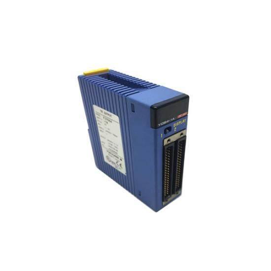
The Yokogawa F3YD64-1A Input/Output Module is designed for industrial control systems, offering reliable signal processing and robust protection against short circuits. Ideal for manufacturing plants, energy facilities, and other heavy industries where precision and safety are paramount.
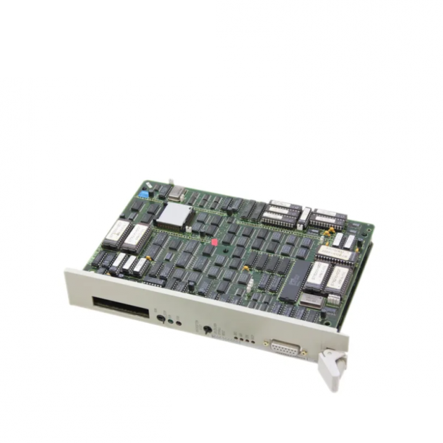
The SIEMENS SIMATIC S5 CENTRAL CONTROLLER MODULE 928, model 6ES5928-3UA12, is a robust and efficient modular component designed for industrial automation systems. It offers advanced functionality and connectivity options for streamlined control applications.