

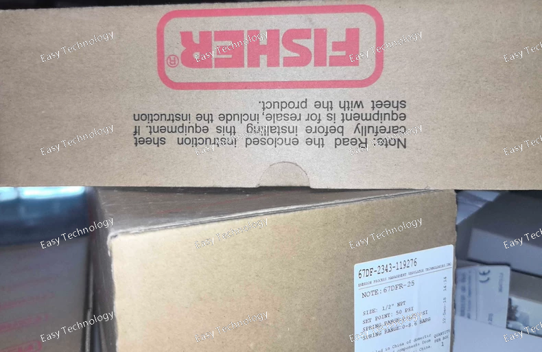


The Emerson KJ2003X1-BB1 12P3439X032 New Module is a high-performance industrial control solution designed for advanced automation systems. It offers seamless integration and enhanced system reliability in a variety of industrial settings.
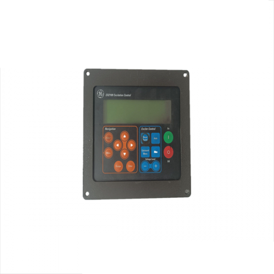
The GE Fanuc IC752SPL013BB is an advanced excitation control panel designed for precise voltage regulation in industrial applications, ensuring optimal performance and reliability in power systems.