Parameter Category Specification
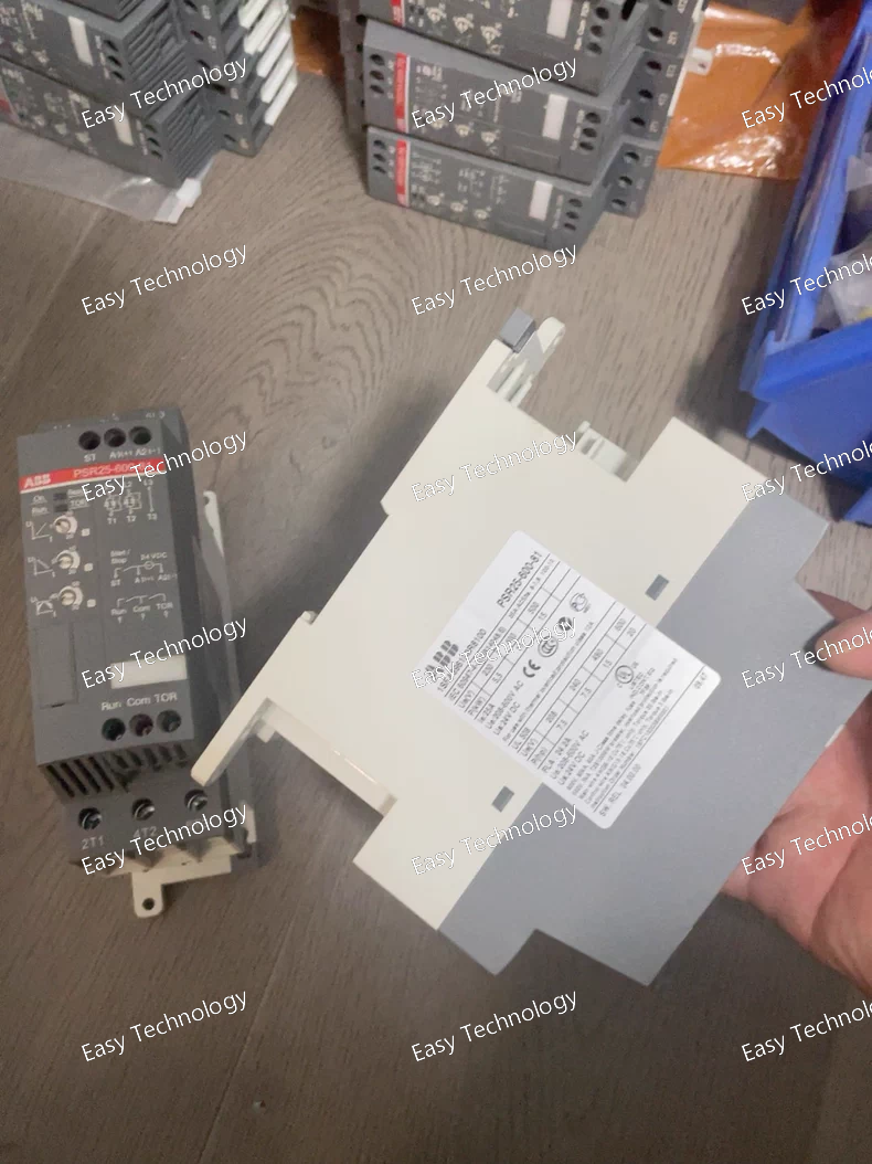
Product Family / Type Numerical Motor Protection Relay (Electronic Overload Relay)
Standard Compliance IEC/EN 60255, IEC/EN 60947-4-1, -8
Rated Auxiliary Supply Voltage (Us) 48 - 250 V DC / 48 - 240 V AC, 50/60 Hz (Auto-ranging, suffix -70)
Rated Motor Current Setting (Iu) 0.1 A - 1000 A (Wide setting range, independent of hardware). The -600- in the code typically indicates the factory default or compatible CT secondary rating of 1A.
Current Sensor Input Accepts signals from standard 1 A or 5 A secondary Current Transformers (CTs) or Rogowski Coils.
Core Protection Functions
• Thermal Overload (49) Digital thermal replica model with separate heating (during run/start) and cooling constants. Adjustable Iu (Full Load Current), Trip Class (5…40), and Ambient Temperature compensation.
• Phase Unbalance / Loss (46) Protection based on negative-sequence current calculation.
• Short-Circuit / Instantaneous OC (50) High-set, instantaneous trip for short-circuit protection.
• Earth Fault (50N/51N) Residual current protection (via Core Balance CT or calculated). Can be set as instantaneous or time-delayed.
• Locked Rotor / Stall (48/14) Separate stall protection with adjustable stall time.
• Start-up Supervision Monitors start time and protects against prolonged starts.
• Number of Starts / Restart Inhibit Programmable limits to prevent motor overheating from frequent starts.
Configuration & Interface
• Front Panel Controls Rotary Switches for setting Iu, Isd (Short Circuit), t6x (Stall Time). DIP Switches for enabling functions (Earth Fault, Unbalance), selecting CT ratio, and setting Ie (Earth Fault current).
• PC Software (Optional) ABB PSRsoft for advanced configuration, real-time monitoring, and data logging via the front USB port.
Output Contacts
• Trip Relay (CO) 1 Changeover contact (95-96 NO, 97-98 NC).
• Alarm Relay 1 (CO) 1 Changeover contact, typically pre-assigned to Thermal Pre-alarm (e.g., at 90% thermal capacity).
• Alarm Relay 2 (CO) 1 Changeover contact, programmable for other alarms (e.g., Unbalance, Earth Fault, General Alarm).
• Binary Inputs 2 programmable inputs for functions like External Reset, General Alarm Input, or Underload Enable.
Monitoring & Indication
• Measured Values Phase currents (L1, L2, L3), maximum current, earth-fault current, thermal capacity used (%), motor status.
• LED Indicators 7 LEDs: PWR (Green), TRIP (Red), ALARM (Yellow), START, RUN, COMM, G.ALARM.
• Fault Memory Stores the last fault type (Overload, Unbalance, Stall, Earth Fault, etc.).
Communication (Optional) Can be equipped with a plug-in communication module for: Modbus RTU (RS485), Profibus DP, or DeviceNet.
Motor Thermal Memory Includes a supercapacitor to retain the thermal memory and clock for several hours in case of auxiliary power loss.
Operating Temperature -20°C to +60°C
Storage Temperature -40°C to +85°C
Mounting Standard 35mm DIN Rail (EN 60715).
Housing & Protection Plastic housing, IP20 protection degree.
Dimensions (W x H x D) Approx. 70 mm x 125 mm x 121 mm (4 module width = 70mm).